Hard to believe that it’s been over 8 years since my last major design of a portable N64. I mean to put that in perspective, the portable version before that was a vacuum-formed and frankencased monstrosity that might as well have been held together with bubblegum!

But after the Cross Plane project finished up at the end of 2013, I found myself for the first time with access to new maker tools that were just starting to come within public reach. And those tools were of course, 3D printers and low volume prototype boards for custom electronics.

Although this crossed over with my CNC efforts which had begun to take hobby vacuum-forming to the next level, the ability to design from the inside out was just too enticing and thus CAD and 3D printing took over and it was only a matter of time before I circled back to the N64 with these new methods.

Fast forward now to the better end of a decade, and not only am I back with a brand new Nintendo 64 portable, but one that uses more fabrication techniques than I could have ever believed I’d have access too.

I first have to acknowledge though that this build was not a sole effort on my part, nor have most of my projects over the past decade. And in this case, I collaborated with some of the best in the business when it comes to portable making, and in fact some of those whole actually made portable making a business.

A huge heartfelt thank you is owed to Gunnar (Gman) and Aurilio of Bit Built and 4 Layer Tech for all their help with the shit I don’t understand! That of course mainly being circuit board design and firmware, to which the entire new system was based around.

TECH SPECS

While the video above does go though the system and some of its key new features, it doesn’t go too into detail with how it’s made or specifically what’s under the hood. So for those who like that kinda thing, here we go.

Enclosure – As per the standard, the base is made up of (7) 3D printed parts. A front and back face plate, a front and back face bracket, a cart cover and 2 battery covers. Also 7 bracket clamps hold the two ends together with flathead machine screws.

Buttons – The actual buttons on this one are all SLA 3D printed in clear. And though the R/L & Z buttons use the traditional soft top tack switches, the rest took advantage of having a real PCB motherboard and used the conductive rubber membranes like the pro’s use! We’ll get to that in a bit, but for the R/L & Z, I had to rethink how the best way to mount them to the case would be. Not tryin to brag, but this side-channel bracket system not only fit well with the design, but the feel and responsiveness is on par with a real controller. So simple, yet so effective!

Display – The display is the one thing that I have not changed. It uses the same 5″, 4:3 Aspect Ratio display as many others. This first set-up only uses the standard composite display, which isn’t the best but does the job.

Screen Protector – This is the first time I’ve used this technique on an N64 portable, and just like the experience I had with the Tiger Boy Advance, I found that custom artwork printed on Self-Adhesive Vinyl gave the sharpest result. This allowed for the used of a plain, non-printed, piece of CNC cut acrylic to be used as the lens itself, which simplified a lot of the cut and print process. Figuring out how to make the backlit logo shine through only when there was backlight was a bit of a challenge.

The Backlit Logo – Blocking out only certain parts of light is a challenge. My first attempt used a blank piece of CNC cut acrylic with the Nintendo logo cut out of a black self adhesive vinyl and applied to it. While this did the trick, it wasn’t as clean as I hoped and the new versions take advantage of Layered Printing, with the blackout layers built right in.


The PCBs – This of course was the big one and their design and testing took a majority of the overall time it took to get this project completed. Aside from the main motherboard, there were 3 Sub-boards specific to this design. A power/volume board at the base, an LED board for the logo back light and a backer board for the new Cart Slot FFC.

The board also was designed around (3) 4 Layer Tech boards. The “U-Amp 2”, A “PMS-Lite Rev E” and a soon-to-be released N64 controller board that uses an original N64 controller chip, but has a multiple set-up options for custom configurations as well as built in FRAM for game saves.

This particular controller config is set up for a Nintendo Joy Con control stick, with programmed dead zone and drift reduction, along with a hotkey that allows recalibration if need be.

The U-Amp is also very cool because it supports a switchable headphone jack. We all miss the headphone jack, they is no deigning! The speakers themselves are also new to me, but they are the same ones used in the original GBoy kits. Not at powerful but they work.

These three boards solder directly to the main motherboard, which makes the once tedious wiring an absolute breeze!

USB C Charging – One of the main benefits of the PMS-Lite is its ability to support USB-C charging with Power Delivery. This allows for the use of a very standard charging solution that is available almost everywhere and can really speed up the process.

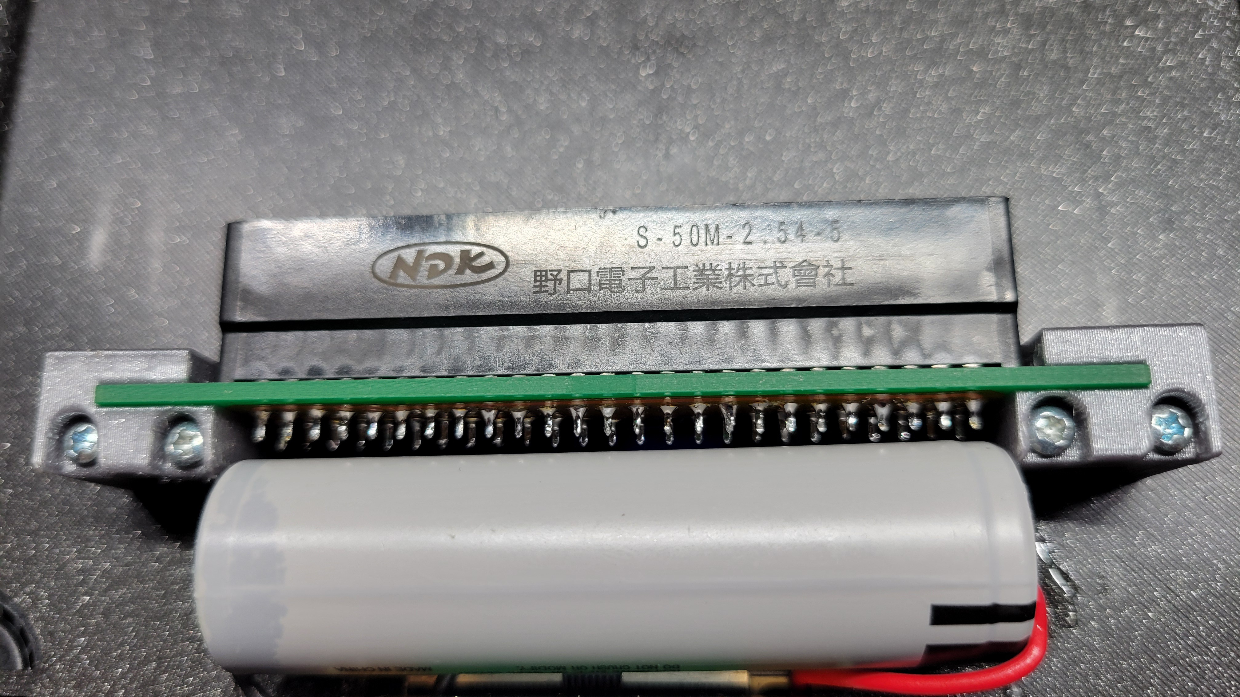
New Cart Slot FFC – This is a redo of the original FFC cart slot relocation that was originally done by RDC. The problem with that version is that the trace length was really maxed on certain pins and just not a very consistent length. The video does a good job explaining what we had to do to make this work as intended!

Battery Power – The system is powered by (3) 3.7v Li/Io18650 battery cells. Originally the idea was to power it with just two, but since I’d never used them before, I had no idea how little battery life they had in comparison to the 7.4V Li/Po flat cells I used to use. I learned a few important lessons about Volts X Capacity to = Watt/hrs, so a third cell needed to be added and it was all a matter of luck that it actually fit!

The N64 – As before, the main system is a moderately trimmed N64 main board. No crazy RCP rewiring or expansion pak relocations. Using CNC to manually trim is one of the best things ever!

I’ll more than likely be adding to this post with things I forgot or be making additional posts about this in the future, but hopefully this gives a pretty good overview of what this project took to complete! I appreciate you as always and if you have any questions or feed back, send ’em my way!

Hey everyone! So I just wanted to give a bit of supplemental content to my last project. Though I put a great deal of time into the first video, this is just quick and dirty overview of some the play modes and features that I didn’t include in the first one.

Hope you enjoy!

Well Merry Christmas! Nearly two years to the day since the inspiration to take on a project like this first was ingrained, I’m finally calling this mini Air Hockey table “nearly” finished. And what a process this has been!

15 years ago, had someone told me I’d be even thinking of making something like this, much less actually pulling it off, I’d have looked at them sideways. But that’s what I love about this hobby. It allows even the craziest of ideas to actually stand a chance of becoming a reality.

Top view of the table.

The concept of the table is the same as real Air Hockey, however as is apparent, it is mini and is only about 1/5th the size of a normal Air Hockey table, and uses a 2.5″ puck vs the standard 3″.

Where things vary even more are its theme and play features. As you may have noticed, there are several references to the Doom Slayer all over the physical table as well as in the play features. So I guess you could call this a “DOOM” themed table.

The table operates in one of three play modes that are switched by the control panel on the side (seen below)

Mode #1 is your standard air hockey experience, where two players compete in a “first to 7 points” match. The LED array on the table is set to match the layout of a standard hockey rink and the sound effects when a goal is scored are standard horns and buzzers.
Mode #2 is Doom Hockey Mode, which uses the same rules as standard Air Hockey, however the LED array turns to a nice fire effect while the sounds of goals scored are either demon screams from Doom or the Doom Slayer screams, depending on which player scores!
Mode #3 is Emulation Mode, which basically takes over the score board display and allows you to play any game that can run on a Raspberry Pi 2B and Emulation Station. It’s a neat little feature that gives the whole unit a bit more versatility as a gaming station.

But we took this a bit further with the help of a composite video capture card, that not only grabs the screens output, but it also sends that signal down to the LED array on the table and recreates the video there…kind of.

So it should go without saying that this was probably one of my most ambitious projects I’ve ever taken on. Not just because I’d never attempted anything like it before, but also because I knew it wouldn’t be possible for me to do on my own.

The Control Leg for Play Mode Selection, Main Power, Blower Power and Volume Control

That said though, aside from shelving the project for almost a full year, the way everything came together throughout the course of the build was, in my opinion, remarkable!

There were so many different types of materials, layers and fabrication methods used to make up the physical table, all of which would have to tie into one another perfectly. But knowing there would be soft automation, lighting and a physical/software combined user interface only added to the potential list of things that could go wrong. 

I had never really combined 3D Printing and CNC Machining the way I had to here. For example, when it came to mounting the side legs, the screws had to line up through 5 different parts and 4 different materials!

This made the 3D Modeling that much more imperative because being able to use the actual models to generate the cut paths for the CNC as well as the STL files for the 3D printed parts made life a great deal easier when it came to the physical assembly.

It was particularly handy when it came to parts like the table top that required actual printing as well. Having a defined cut path ahead of time gave me the boarders for the print so I wouldn’t cut anything off when I put the parent sheet on the CNC.

The Raspberry Pi was the second level of this build, which is pretty much where my usefulness ended. And as I mentioned in my video, I have to give a huge shout out my buddy CrashBash for taking the lead on this one, as his work not only brought the LED table to life but also gave the table its soft functionality for the score board and user interface.

And though the LED functions are awesome, the real benefit was the backend handling of the automation I wanted to include, like score detection/tracking and the play mode user interface. To make this work though, the Pi obviously needed some kind of way to receive input that either a goal was scored or the play mode changed. The play mode was pretty easy as they were just simple tact switches but the score detection was a bit more of a challenge.

This was the pinout we used up until we had to add a Pi Pico to the mix to get the scoreboard legs and LED back lights to work properly.

I first had attempted to use simple lever arm limit switches for CNC machines, but getting them to trigger consistently in the puck traps was a bit of a problem. This is when I came across the IR LED Break Beam Sensors from Adafruit. These provided a more reliable solution, though is still not 100% as the traps were too wide for a single LED to cover. So two were wired up in parallel in each trap which I think sometimes causes a bit of confusion.

So that’s really just a taste of what went into this project and and I could go on and on about its features, but ultimately, I’m just amazed we were able to pull it off! Overall I’m very happy with how this came out especially with all the unknowns that both Crash and I were up against.

It’s still not perfect, we do have some emulation issues to work around and the score detection sometimes fails to count a goal which can be worked around easy enough, but other than that, I’m stoked to have this finally complete!

I’ve got several other projects well into development, so the first few months of 2024 are looking to be a good one! Thanks for checking this out and I’ll see you next time!

That’s right! For the first time ever, I will actually be giving away one of my portable console creations! This is a pretty big deal for me in many ways, but as thank you to all who have been supportive to the console modding community, you now have the chance to enter into the giveaway!

Check out the video above for all the rules and restrictions and as always, feel free to drop me a line with any questions!

Along with it, a new video I’ve been working on for a couple months now!

I can’t believe it’s been nearly a year and a half since I’ve released a proper video and though the content is similar to my last system, this video kind of combines both the remake of this system and the experiences of the Midwest Gaming Classic 2023.

Not a whole lot here to say that the video doesn’t cover so I’ll let that do the talking, but I just want to go on record that I’ve missed doing this kind of thing with a passion.

Headed to MGC 2023!

Posted: 02/12/2023 in Uncategorized

It’s coming up on that time of year again and for the first time ever, I’m making it out to two consecutive Midwest Gaming Classics in a row! I had such a blast last year and it would be so cool if I could do this annually but it is quite a haul and quite expensive for just the weekend. But getting to hang with my modding buddies like this really is worth it and gives me the chance to meet even more amazingly talented people.

That said, I’ll also be presenting again on the Bonus Stage, which last year was hosted by the awesome guys at “Hair of the Dogcast”. I learned a lot about what to expect for crowd and environment and this year will be tailoring the presentation to that. The main difference though is that I will not be solo presenting and talking to a room of roaming people who really were not paying attention. I will be joined on the stage by this year’s Bonus Stage host, Seth, from the TigerChainsaw You Tube channel.

Seth will be taking over for the Hair of the Dogcast crew this year as they could not make the show because they had to be good friends or something… But that’s ok, because they have been working with Seth to make sure the stage is run as smoothly as possible and from checking out Seth’s You Tube, I look forward to working with him!

So as I mentioned, unlike last year where I just monologued a story to a very passive crowd, this year I’ll be actually engaging with Seth about the early history of console modding. So I’m looking forward to this a great deal in many ways! And the stage is actually going to be located in a higher traffic area right next to the food court.

I’ll of course have a report on how this whole experience plays out but its already shaping up to be an amazing time! More to come soon!