Part III – Power and Cart Slot Wiring
- Preparing the Cart SlotBefore wiring begins, there is a bit more prep work to be done to the cart slot. The plastic mounting pins that held the cart slot and DD slot in place needs to be trimmed down so that it mounts correctly with the Cart Slot Mounting Brackets. We also need to trim the plastic facing on the front of the cart slot to make sure the game cart itself stays nice and tight to the back of the actual casing.

First we need to flush cut the two mounting pins off the cart slot.

A rotary tool and a cut wheel is the easiest way to do this, but diagonal pliers and a file will do the same job.

Then we need cut the plastic facing off the front of it.

In order to ensure the cart slot cover fits properly and the game moves around as little as possible, cutting this front plastic lip off is essential. Make a cut about halfway down on the edge as shown to be sure the left over plastic is below the metal line. Also make sure the side you cut has the triangle and numbers printed on it. Once both edges are cut, pull the face off or pry off with a flat head screwdriver as it will still be connected with a few plastic tabs.

Make sure your cut on the mounting pins is as flush to the base of the bracket as you can get.

When your cut on the two edges is complete, make sure that entire face is flush with the newly exposed metal jacket.
- Wiring The Cart Slot

The cart slot is one of the most labor intensive parts of the project aside from the case work. While there are short cuts that can be taken, the recommended practice is a 1 to 1 rewire of each pin to the board to make sure it’s running just like factory new. Though this is not a hard part of the project, wiring 48 pins one at a time can get a bit tedious, but is the safest way to do it right.
30 AWG Wire Method

The conventional method of cart slot rewiring, it requires cutting 48 wires, stripping both ends, tinning both ends, tinning the pins on the cart slot, tinning the solder points on the N64 and soldering the wire directly to a pin on the cart slot to the corresponding solder point on the N64. As I said, this is a tedious process but one that has been tried and tested over the years. Though the spacing is pretty generous between the pins, you still have to make sure that you have no solder bridges and that your connections are very solid, otherwise shorts could occur and cause issues.
- So to start with, you’re going to need 48 cuts of 30AWG wire at about a 5″ inch length. You don’t want to go much longer than that as it can cause issue and you’re going to want to make sure they are all as close to the same length as possible.
- Strip the wires back about a 16th of an inch on both sides, being careful not to strip too much more as less exposed wire means less chance of a short.
- Tin both ends by applying some flux to both ends and then applying a little bit of solder to the wire ends.
- Repeat the tinning process with the cart slot pins and the solder points on the N64.
- You should now be prepped to start hooking wires up directly. .
Optional Short-Cut: The 27 Wire Method
The 27 Wire Method was discovered by a fellow modder under the title of “Bungle” a few years ago. He found that most of the pins on the connector were actually just redundant grounds which could be omitted, saving both wiring time and space.
The Green Dots are the pins that are required to wire, while the Blue Dots connected with the Black Line were all ground pins and all the Blue Dots connected with the Red Line were 3.3v.
He suggested that if you were to omit all the blue dots and use pin 1 for the main ground and pin 9 for the 3.3V and used a thicker wire gauge to make up for all the other wires no longer connected, the same result could be achieved with far fewer wires.
Again this is optional and other modders have had success with this, but I find it better to wire everything up the way it was originally connected.
TIP: The pic below is helpful if you do get the same color wire to correspond with the connections. Using black for ground, red for power and green for the signal pins will make trouble shooting a great deal easier as most issues with the cart slot will be narrowed down to the green wires.

- Wiring The Batteries
NOTE: This process is also under revision. This section will be updated once complete.
Wiring the batteries is a process you should take your time with, being the natural volatility that Lithium/Polymer batteries potentially have if installed incorrectly. Being sure to properly insulate all solder connections and securing all power lines firmly will help avoid very nasty shorts or other damage causing issues like explosions or fire. If you do not feel comfortable with this step, do not proceed until you’ve done more research or consulted with someone who knows what they are doing.
The diagram below shows what we need to do to get the batteries wired in series to give us the 7.4v we need to run the system. It is recommended you use 22 AWG wire in Red and Black to keep your live and ground lines separate. Do not use anything smaller that 22 AWG for power (i.e. do not use the 30 AWG that you used for the the cart slot and will use for the controls) as this can cause bottle neck issues and potentially cause damage to the system.
***NOTE: Once the batteries have been wired to the protection circuit, by default, the protection circuit is going to cut the output, which if you don’t know ahead of time will lead to hours of trouble shooting trying to figure out why you can’t get any power to the system. The protection circuit will continue to keep the power cut until the 7.4v smart charger is connected which closes the circuit to the batteries and then allows power to flow, at which point you should be reading anywhere from 7.4 to 8.4V on a full battery charge.
The other thing that needs to be considered is that in this wiring diagram, the batteries are directly connected to the battery jack. This serves a couple functions. Having the batteries before the main on/off does allow for us to charge the batteries without needing the switch to be in it’s own dedicated position and also if you had the wall power plugged in, you could play off wall power while the batteries charged. However, that also means that you will have a live 7.4v coming out of the battery jack. If nothing is connected, nothing is going to draw and your battery is not going to drain, but you could in theory cause a short if you got some kind of conductive material in the jack itself and bridged the ground/power. Chances of this though are very rare, but is something that needed to be mentioned.
***NOTE: THIS METHOD LISTED BELOW IS FOR THE LEGACY VERSION OF THE SYSTEM. NEWER VERSIONS HAVE THE CUSTOM CHARGER BOARD WHICH USES JUST A SINGLE POLE/SINGLE THROW SWITCH AND A SINGLE BARREL JACK. NO SMART CHARGER IS REQUIRED FOR THAT METHOD. BATTERY WIRING TO THE PROTECTION CIRCUIT REMAINS THE SAME. AN UPDATE WILL BE POSTED SOON.


Lay the two cells side by side and secure the protection circuit to the left cell as shown with a bit of hot glue.

Using electrical tape, secure the two cells together as shown, making sure you don’t cover the protection circuit.

The contact tabs on the batteries are a little long. You can cut or fold them over but make sure they don’t go beyond the edge of the battery. Wire the right cell’s negative (black) pad to the B- on the protection circuit. Then, wire the right cell’s positive (red) pad to the Negative pad on the left cell. Use this pad as a junction and use a short wire to then connect to the Com pad on the protection circuit.

Wire the Positive pad of the left cell to the B+ pad on the protection circuit. Then connect two 6″ leads to the P+ and P- pads as shown.

Cover the leads with more electrical tape to complete the battery pack.
- Connecting Batteries and Wall Power to The Main On/Off Switch & Grounding
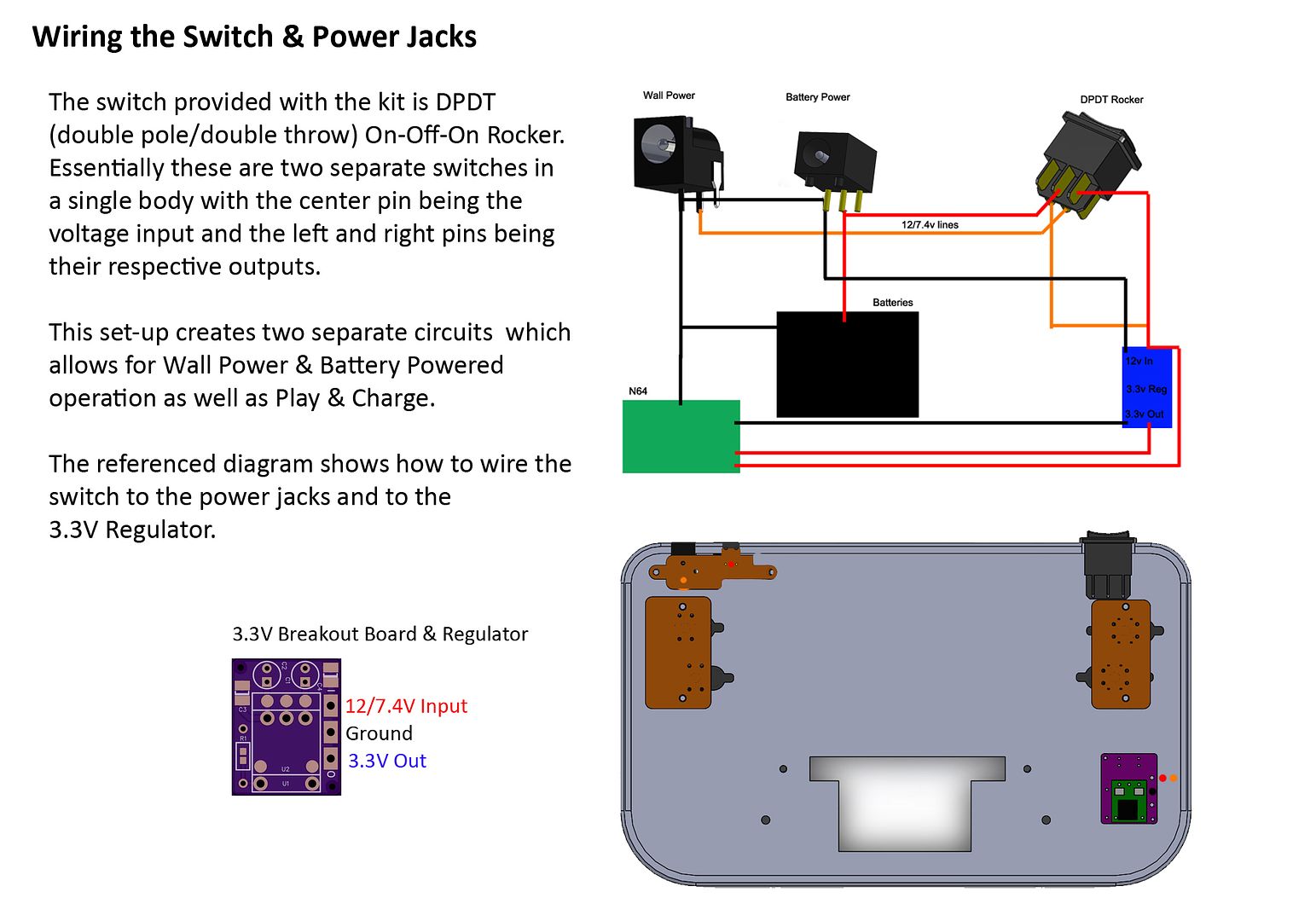
The below diagram shows how to connect the wall power and battery power jacks to the main On/Off switch for the whole system. Here you choose which way you want to power the system using the switch. With this wiring set up, pressing the switch to the left will give you wall power, in which case you’ll have to have the 12V adapter plugged into the wall power jack, or pressing right to run off of battery power.
Please NOTE: This is the Legacy Version of the system. Do not follow this method if you have the Custom Charger Board. A guide on that method will be posted soon.
Grounding – This is another important part of the wiring process. The N64 uses a common ground set-up which means everything from power to signal lines are all grounded to the same place. The above diagrams shows every ground line needed to function as far as the batteries and power are concerned. Controller, screen, audio amp and speakers also will end up connected to the same grounds one way or another, mainly through the N64 board.
- Wiring to The 3.3V Regulator and The N64 Motherboard
The 3.3V regulator included in the kit is just a TI PTH08080WAH variable step-down regulator on a custom breakout board. This breakout board supports both a Surface Mount or Through Hole configuration which is useful if your project requires tighter height tolerances. For the kit though, the Through Hole will fit just fine so all parts for the regulator will be included and just need to be assembled.

PTH08080WAH Thru-Hold Regulator on Custom Breakout Board
Please make sure you have reviewed, assembled and tested this regulator before wiring any power to the system.
What I like to do is use this regulator as a “HUB” for the power distribution throughout the system. By that, I mean the 12/7.4V pad acts as both an input to the regulator, but also an output for the 12/7.4V to the screen and the 12V line to the N64. The N64 runs off of two voltages, 3.3V (hence the need for the regulator) and 12V (but will run as low as 7.4V).
With this board trim, you are actually able to wire directly to the original power output points as the original switch on the system for the 3.3v line and be done. The diagram below shows what points each voltage is supposed to go to. However, the 12V line gets severed by this board cut, so we have to do a bit of a re-wire to fix that. I’m not 100% sure if the 12V trace actually powers anything important up to the point the cut was made, but in the interest in keeping the trace fully powered as needed, wiring a jumper wire from the point of the cut to the point shown on the diagram will work just fine.
